Background
This post is a follow-up from my previous post Building Radar Speed Camera and Traffic Logger with more information, improved design and experience from using the device in the field for nearly 2 years.
This project is a self contained speed radar that can be used to give realtime traffic speeds, log traffic flows and statistics over a period of time and also possibly capture speeds of other objects in sporting environments, for example, though I haven’t specifically tested and tuned the code for this. I don’t want to repeat the information in that post so please read that one first if you’re interested.
The aim of this new implementation is to make the fixed installation of the previous more flexible by fitting it into a box with a display and running from battery power.
Construction Guide
Parts List
- Raspberry Pi, nothing fancy a Pi Zero will work. You will also need an SD card, power supply and maybe a WIFI dongle for this.
- 24Ghz Stereo Doppler Radar Module RMS-2650
- 2x LM386 amplifier module
- very clean 5v power supply
- Ground loop isolator with 3.5mm audio jacks
- 3.5mm jack socket with wires attached
- USB soundcard with line-in
- 170 pin breadboard
- 1602A LCD Display with i2c connection
- 10x Female-female breadboard patch cables
- 10x Male-female breadboard patch cables
- plastic enclosure
- USB power supply / battery pack
- 4700uF Electrolytic capacitor
- micro-usb connector jack
Tools Needed
- none
Follow these steps to build the radar hardware without needing to solder:
- connect 2 female-female patch cables from RMS-2650 radar module to IN connection on the two amplifier modules
- connect power supply pins on RMS-2650 to breadboard using male-female patch cables.
- connect power supply pins on amplifier modules to breadboard using male-female patch cables.
- connect micro-USB connector jack to breadboard such that radar and amplifier modules will be power by 5v supply from USB.
- attach capacitor to breadboard on 5v supply from USB observing polarity.
- connect outputs from amplifier modules to 3.5mm jack socket.
- connect 3.5mm jack socket to input side of ground loop isolator
- connect output of ground loop isolator to sound card line-in.
- wrap ground loop isolator in aluminium foil and connect to ground on breadboard.
- connect sound card using supplied USB cable to Raspberry Pi.
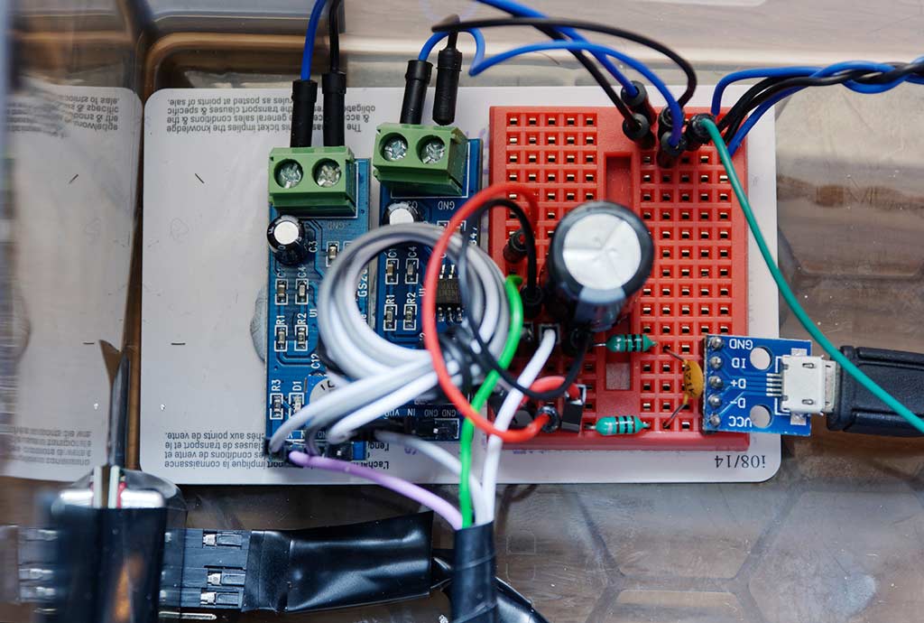 Figure1: Radar module with dual amplifiers
I experimented a bit with different power supply options for the system. The problem is that the radar module is quite sensitive to electrical noise and the Raspberry Pi, especially with WiFi connected is quite noisy. A completely separate power supply helps a great deal but adds to the cost and complexity.
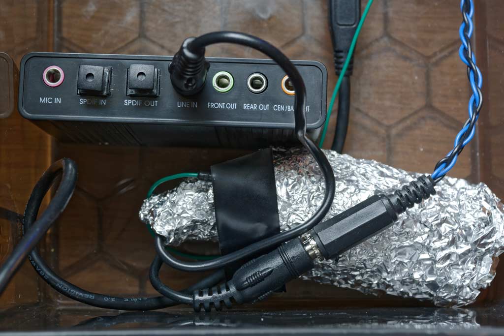 Figure2: Ground loop isolator and USB soundcard
The ground loop isolator helps significantly with eliminating noise too. It is important that this is wrapped in foil to act as a faraday cage to stop stray electromagnetic fields.
Setting up Raspberry Pi
The sound card should be automatically detected by Raspbian. When it is attached if you type lsusb you should see:
> lsusb
Bus 001 Device 004: ID 0d8c:0102 C-Media Electronics, Inc. CM106 Like Sound Device> aplay -l
* *** List of PLAYBACK Hardware Devices *** *
card 0: ALSA [bcm2835 ALSA], device 0: bcm2835 ALSA [bcm2835 ALSA]
Subdevices: 8/8
Subdevice #0: subdevice #0
Subdevice #1: subdevice #1
Subdevice #2: subdevice #2
Subdevice #3: subdevice #3
Subdevice #4: subdevice #4
Subdevice #5: subdevice #5
Subdevice #6: subdevice #6
Subdevice #7: subdevice #7
card 0: ALSA [bcm2835 ALSA], device 1: bcm2835 ALSA [bcm2835 IEC958/HDMI]
Subdevices: 1/1
Subdevice #0: subdevice #0
card 1: Device [USB Sound Device], device 0: USB Audio [USB Audio]
Subdevices: 1/1
Subdevice #0: subdevice #0You may need to configure ALSA to make the USB sound card your primary sound card. See this page for more information as this seems to change with different versions of Raspbian. On the (currently) latest Rasbian Stretch this page might be more useful.
You should now be able to see the line-in capture device in alsamixer. Run the tool and configure PCM capture to the Line in and make sure gain is adjusted reasonably high:
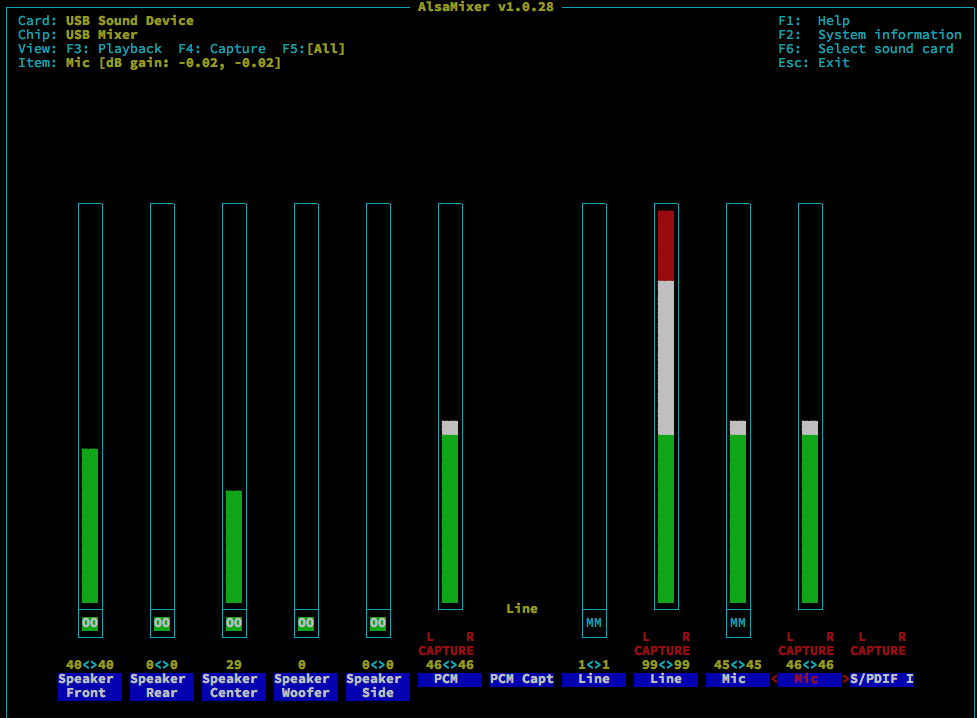 Figure3: Alsamixer
Software
First you’ll need to install the ALSA audio python API and reboot:
> sudo apt-get install python-alsaaudioThen download the code from github:
git clone https://github.com/tonbut/rpi-traffic-radarA ground up rewrite of the original code is found in the version2 directory. I’ve refactored the code so that the core functionality is in a class that can be instantiated with various configurations and with callbacks for various events. This code is python 2.7 compatible so please make sure you use that version otherwise you might see errors like:
SyntaxError: Missing parentheses in call to 'print'In addition the movement tracking algorithm is much more sophisticated now. It will track multiple objects moving at different speeds in different directions. This solves the fairly common case of two vehicles passing in different directions in front of the radar.
Running in a box
Although the photo below shows a 1602A display with soldered connections I later found that you can get these displays with i2c connectivity which makes it much less hassle to connect to the Pi.
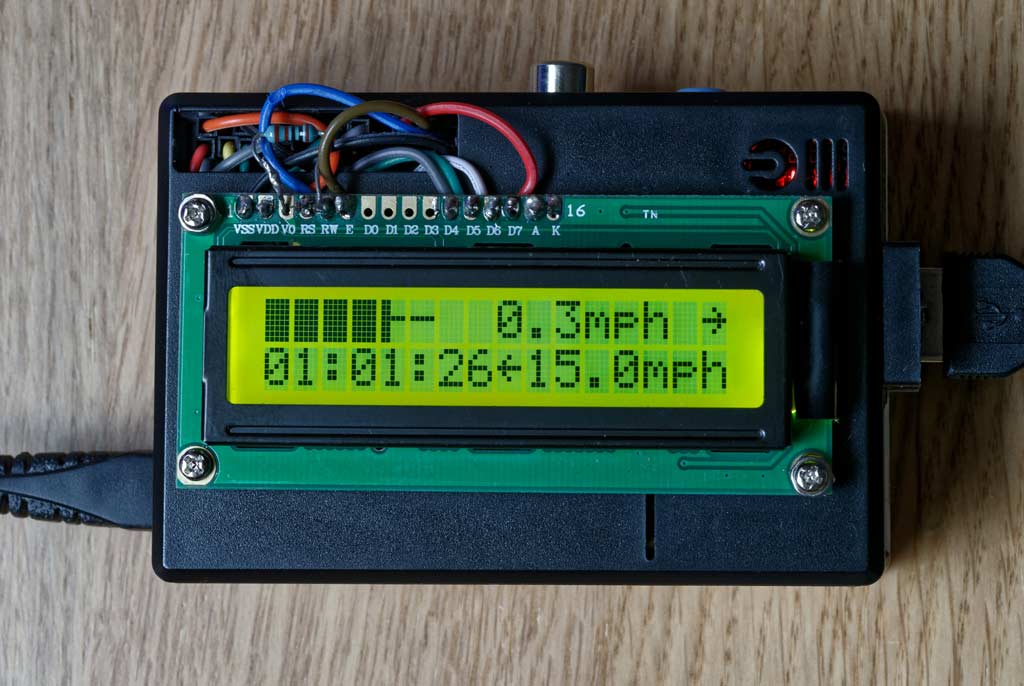 Figure4: Raspberry Pi with LCD Display
See the boxRadar.py example in the github repository for a demo of output the radar information to the display.
Of course you’ll also need a USB battery pack to take this out on the road. Any USB battery pack will do - the project doesn’t use too much power.
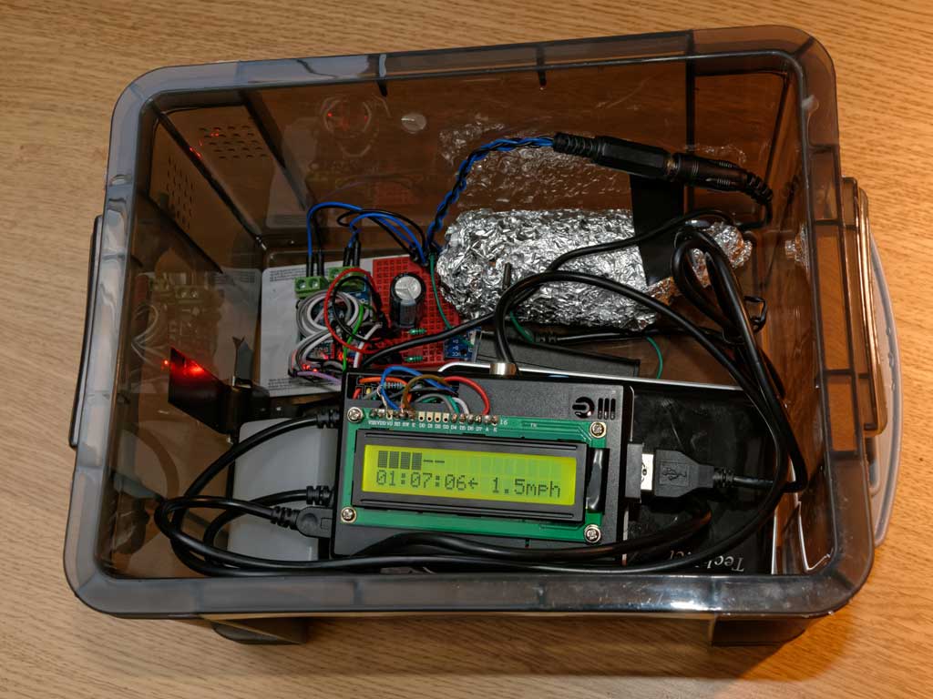 Figure5: Radar in a box
- Header image credit: Takashi Hososhima “A fast car” https://www.flickr.com/photos/htakashi/12345867183 [return]