Background
I’ve had a modest home aquarium for a many years. It has always been lit by a specialist aquarium fluorescent tube. This gave out a nice light which both helped plants to grow and counteracted the excess of green caused by plants an algae.
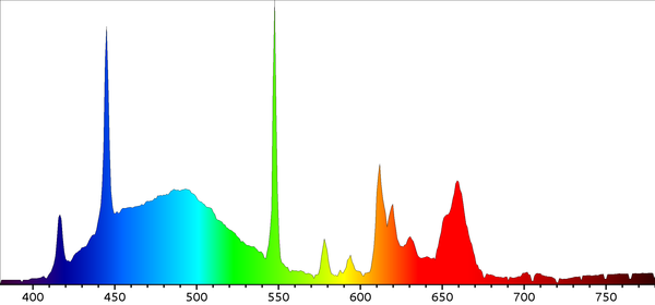 Figure1: Spectrograph of Hagen Aquaglow fluorescent tube
There were two problems with this fluorescent lighting solution however. Firstly, it switches on and off instantly which can be quite unnatural and startles the fish. Actually switching on is worse, the fluorescent starter causes the lamp to flicker whilst starting. Secondly fluorescent lamps and not as efficient as LED, and given that the lamp remains on for up to half the day, that’s a lot of wasted power.
In the last few years LED technology has improved greatly. LEDs are two times more efficient than fluorescent. Last year I purchased some RGB LED strips with a driver that could be remotely controlled. It allowed fine control of red, green and blue channels to create subtle colours that I hoped would be suitable for the aquarium.
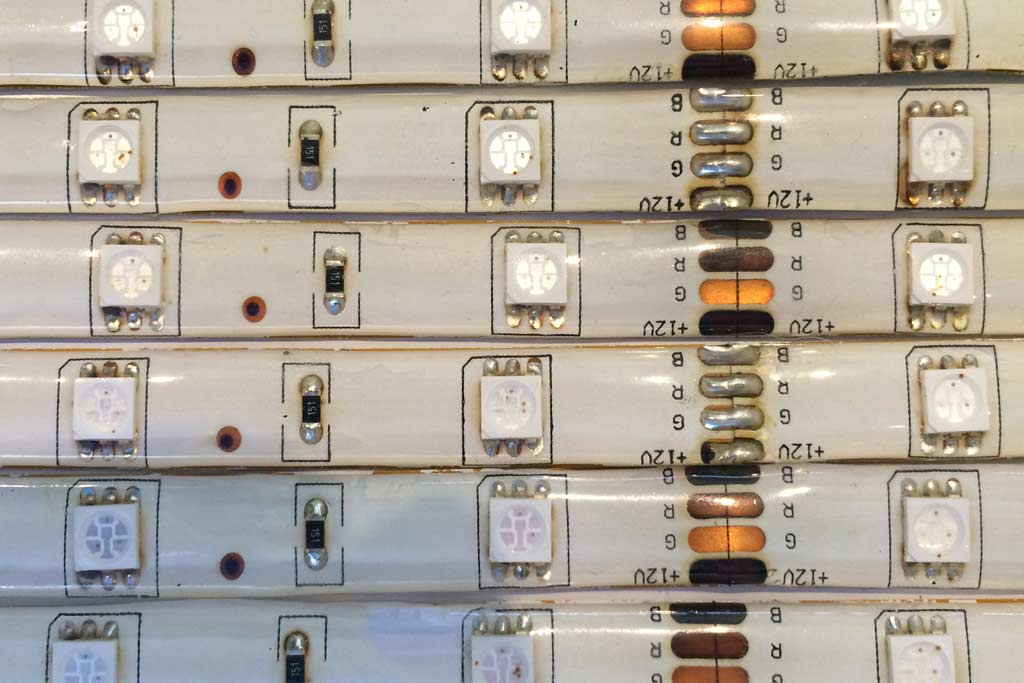 Figure2: 12v RGB LED Strips
The reality of these strips is that they are useless for the aquarium. They are fine for producing vivid primary colours but for subtle whites they just don’t cut it. See my previous rant for more information - in summary: I ended up building a spectrometer.
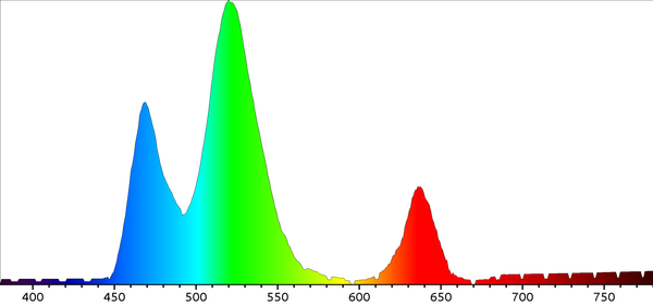 Figure3: Spectrograph of RGB LED strip
I’ve had the idea of simulating the natural daylight cycle for a while now. However it’s only recently that all the parts needed have become available at a reasonable price point.
In particular I needed a low cost wireless micro controller - step forward the Particle Photon. This great little device is easy to program via a web based IDE, it can be remotely flashed over WIFI. It’s pretty compatible with Arduino but has more storage and processing power. Also it’s very cheap - only £18.
I have also been looking for some suitable LEDs. When I saw these EPILED and Bridgelux LEDs that cover a wide range of wavelengths my problem was solved. These discrete LEDs cover the entire spectrum from ultraviolet to infrared.
Design
I’ve evolved this design a little bit whilst building it, however the basic premise remains: a self contained lighting control which can simulate natural lighting whilst giving out suitable wavelengths to promote plant growth.
The design features six channels of light with 10 LEDs in total rather than the more usual three - red, green and blue. These channels are:
- white (a mix of warm and cool white)
- violet and deep blue
- bright blue and turquoise
- green
- red
- deep red and infra-red.
Quite a bit of thought and experimentation went into this choice of channels. As I said previously, I wanted to simulate the natural daylight cycle. This meant being able to produce natural full spectrum daylight but also transition this through sunset into dusk and moonlight. (Ok deep blue moonlight is not natural but it looks good and feels right.)
Also I wanted to be able to optimally create the right wavelengths for photosynthesis and plant growth. The deep blue, deep red and IR LEDs produce wavelengths that most regular LEDs don’t. These are pretty close to perfect for plant growth as well as highlighting pigments in some fish.
The EPILED and Bridgelux LEDs require to be powered by a constant current driver. This means that the voltage supplied to them must be tuned so that the current passing through them remains constant - 700 milliamps. The voltage needed to create this current varies as the LEDs warm up as well as over the lifetime of the LED. Pulsing the LEDs on and off very fast creates the effect of dimming, a method called pulse width modulation (PWM.) The driver modules I found allow for dimming via PWM whilst maintaining a constant current.
Initially in my design the PWM was provided directly from the micro controller. However the Photon is only capable of 8-bit control. Due to the non-linear perception of light levels this leads to the jerky fading of the LEDs at low illumination levels. The PCA9685 module provides 12-bit PWM for 16 channels and is decoupled from the CPU so it can run with a constant frequency up to 1600Hz. It also has, I think, a rather thoughtful feature of allowing you to offset the pulses on each channel. This allows you to smooth the power draw rather than each channel transitioning at the same time.
Construction Guide
Construction is pretty straightforward as it’s just a matter of connecting together the pre-built modules. The only part you really have to be careful about is following the instructions regarding fastening the LEDs to the heatsink correctly. Without proper heat dissipation they won’t last too long.
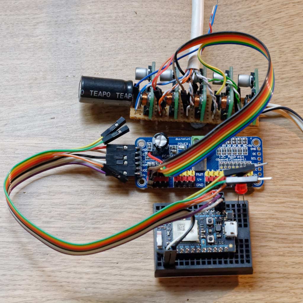 Figure4: Photon particle, PWM module and constant current drivers
Parts List
- 6x 700MA Constant current LED drivers with PCB mount eBay link
- PCA9685 16 Channel PWM Driver I2C Module
- Photon Particle micro controller with WIFI
- Various EPILED/Bridgelux 45 Mil 3W LED Units futureEden.co.uk
- Heatsink futureEden.co.uk
- Veroboard
- Solderless breadboard
- Large electrolytic capacitor ( > 10000uF) rated over 12V
- 12v 3A power supply
- 500mA USB power supply with micro-USB connector
- Thermal Adhesive (Arctic Silver Alumina)
- 12 core cable for connecting LEDs to drivers
- Male-female patch cable ribbons (at least 13 way)
Tools Needed
- soldering iron
- wire cutters
- junior hacksaw
- 4mm metal drill bit
- Alcohol wipe
Step by step:
- Mount Particle Photon onto breadboard.
- Connect PCA9685 to Photon using 6 way ribbon cable. Connect VIN on Photon to V+,VCC. Connect GND on Photon to GND,OE. Connect D0 on Photon to SDA and D1 to SDL.
- Connect the 7 way patch cable ribbon to header on PCA9685 with first 6 cables to connect to PWM on channels 0-5 and the sixth connected to GND.
- Cut the Veroboard to at least 7 x 30 holes
- Solder the constant current drivers onto the Veroboard (all oriented the same way) with a spacing of 5 holes between.
- Cut the three tracks using a small drill bit corresponding to PWM input, LED+ and LED- between each driver.
- Solder the capacitor to the tracks corresponding to +VE and GND observing the polarity of the capacitor.
- Solder the 6 PWM wires from the PCA9685 onto the PWM tracks on the Veroboard for each driver.
- Solder the GND wire from PCA9685 onto the GND track on the Veroboard.
- Prepare and solder the 12 wires for LEDs - LED+, LED- for each of the 6 channels.
- Solder the 12v power supply +VE and GND onto the tracks of the Veroboard.
- Drill centre hole for wires and mounting holes in heatsink.
- Clean heatsink surface with alcohol wipe.
- Glue LEDs onto heatsink using thermal adhesive. The adhesive has a working time of about 3 minutes. I found I could fix at most 3 LEDs in this time. It must first be mixed well and then evenly coated onto the back of LED. After application the LED should be pushed down with force and twisted to ensure even and complete coverage. It should then be left for at least 1 hour to cure under compression before moving on. I turned heatsink upside down and placed some heavy books on top.
- Repeat previous step until all LEDs are fixed to heatsink.
- If you haven’t remembered which LEDs are which (they all look quite similar) then you can test with a quick blip of a 3v battery. Then make a note so that we connect the right ones up to the right channels.
- Multiple LEDs can be connected to the same channel by connecting them in series. Each LED causes a voltage drop of 3-4v so with a 12v power supply it is only really safe to connect two in series.
- Solder the cable from the drivers onto the LEDs making sure you thread the cable through the hole in the heatsink first. Be careful to observe polarity.
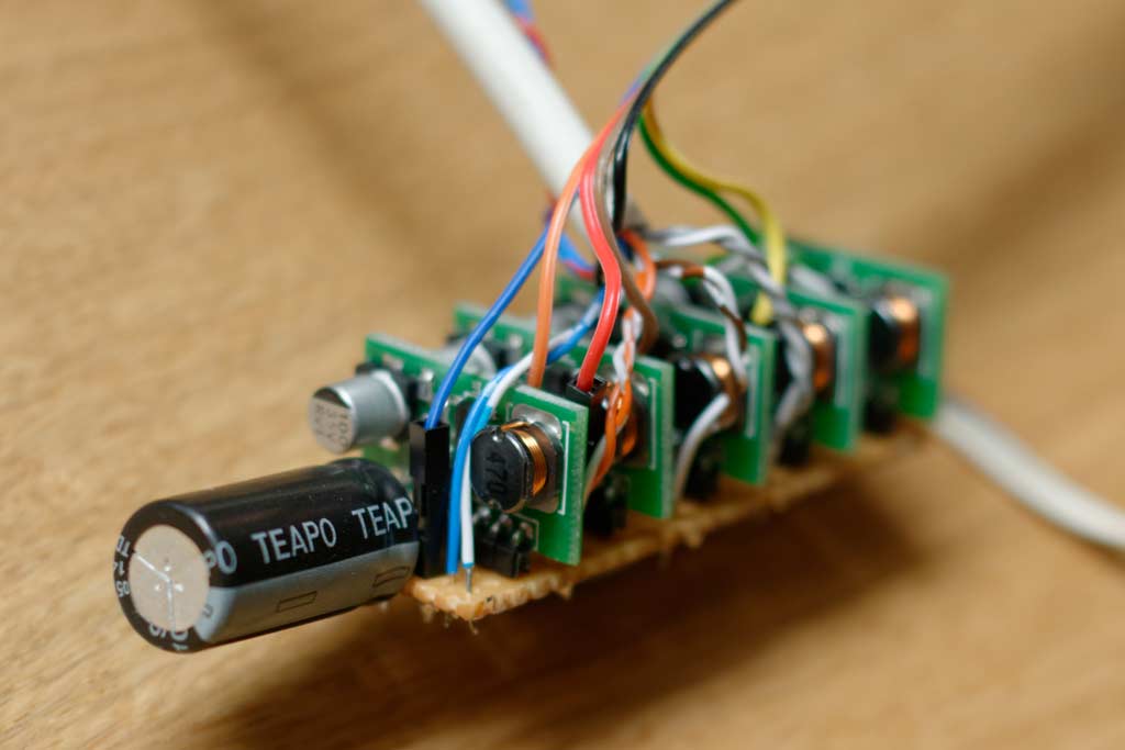 Figure5: Closeup on constant current drivers and capacitor
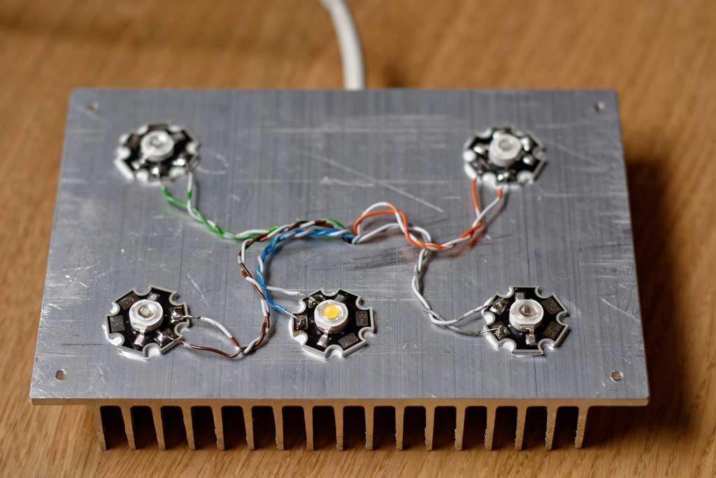 Figure6: LEDs glued to heatsink (initial 5 channel, 5 LED configuration)
Code
The easiest way to put code onto your Particle Photon is to use build.particle.io. I’ve put the source code up on https://github.com/tonbut/PhotonAquariumController. Copy the aquarium.ino, Adafruit_PCA9685.h and Adafruit_PCA9685.cpp files into a new app.
This code also contains a couple of additional features that you can easily comment out. It contains code to read two temperature sensors, one for inside the tank (a DS18B20) and one outside (a DHT22.) Also I’ve attached a light dependent resistor (LDR) to give a feedback loop so I can know if something goes wrong - I really don’t want the lights on all night.
Instructions for use
The controller currently runs for a fixed 24 hour schedule defined in the parseSchedule() function. You should edit this function to suit your needs. It defines a set of times along with a colour value for that time as a CSV string. When the time moves on and into a new colour the colour of the lights smoothly transitions over a 5 minute period.
The time is in the format is HH:MM. The colour format is a hexadecimal value similar to the way colours are specified on websites - obviously, however, with 6 channels rather than the usual 3.
There are a couple of other columns on each row. These are currently unused. (I wanted to have multiple schedules defined, for example for when no-one is at home. I also experimented with a weather feature - see below.)
API
The particle cloud provides an easy secure way to access the Photon controller. You can readily expose variables to be read and functions to be called. The code on GitHub provides a few APIs:
- data - this variable can be read to return the current state of the controller. You can read it from a web browser or from another system such as Polestar.
https://api.spark.io/v1/devices/[PhotonName]/data?access_token=[AccessToken]It returns an XML document like this:
<data time="11:02" schedule="10:00 - 12:00" white="24.0" violet="32.0" cyan="16.0" green="0.0" red="0.0" deepRed="32.0" light="0.290" temp="20.90" humi="59.30" waterTemp="26.81" tempReadingAge="0" waterReadingAge="0" />- setColour() - this function allows you to override the schedule to specify a specific colour. This is useful for experimenting with the lighting schedule. The easiest way to call this is with the command line curl tool to issue web requests. The args argument contains a comma separated string with colour value and a fade duration in seconds.
curl https://api.spark.io/v1/devices/[PhotonName]/setColour -X POST -d access_token=[AccessToken] -d "args=1040404040404,30"- setWeather() - this function allows you to specify a temporary weather situation. The args argument contains a comma separated string with a weather program and a duration in seconds.
curl https://api.spark.io/v1/devices/[PhotonName]/setWeather -X POST -d access_token=[AccessToken] -d "args=3,30"Supported weather programs are:
- 1 - cloudy 1 - the brightness alternates between normal and half brightness with a half second fade time and random period between 5 and 30 seconds.
- 2 - cloudy 2 - every 5 seconds smoothly fade to a new random brightness between 25% and 100%
- 3 - tree cover - every random period of between a quarter and three quarters of second, fade to a new random brightness between 50% and 100%
There is still more experimentation and playing to do here. Some commercial controllers seem to do things like lightning strikes.
Results
The lighting controller is working pretty well. I’ve got an excess of light output with 10 LEDs, so the current schedule only uses about half brightness. When running at this level the heatsink gets to about 40°C. This is pretty safe and could easily work much hotter - the LEDs are rated to 60°C.
I’m really pleased with the quality of the light output - I can achieve perfectly natural colours. Experimenting with the transition to night has been fun too. The lights gradually warm to yellow light and then to a deeper red before falling away to leave a deep dark blue of dusk. Finally this fades away to night.
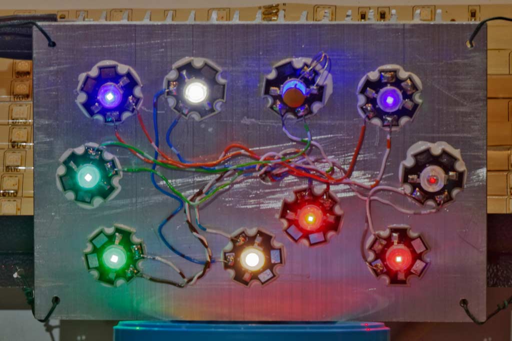 Figure7: Final LED configuration on heatsink
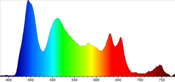 Figure8: Typical spectrograph new LED setup