This post describes my current aquarium setup, in particular, the technical, custom designed parts of it. There is a lot of monitoring and control going on; though virtually all of it is hidden behind the scenes, as my aim has always to create a natural looking environment. An aquarium is an eco-system, some aspects of it can stay in natural balance with maintenance, and other parts require active control. Things are more complicated with plants - I recently have become more serious about growing plants. In many ways, the aquarium is more healthy with both healthy plants and fish, but the plants do require more care and attention than the fish.
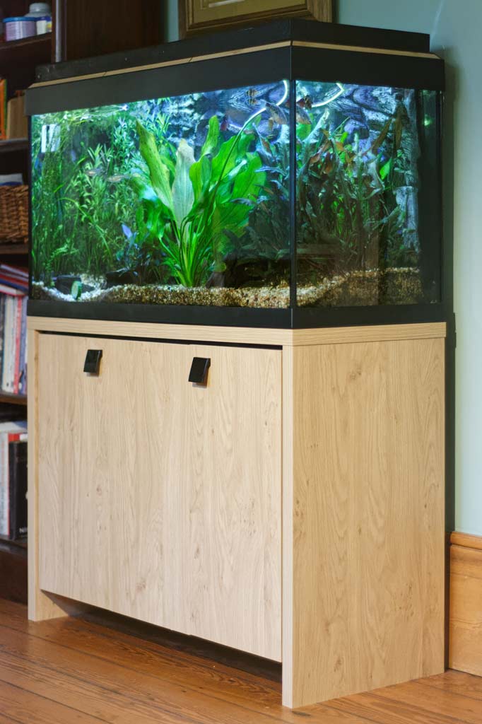
Figure 1: View from the front
You can see from Figure 1 that no technology is visible. The micro-controller and lighting are all hidden in the custom-made hood, the heater and filter piping is hidden behind the rock-effect fibreglass back wall. The remainder of the bulky stuff like the external filter, power supply and co2 tank are below in the cabinet.
Overall architecture
You can see from Figure 2 that all of the sensing of the aquarium is through the Photon Particle micro-controller. This is an Arduino like board with built-in WiFi and a great cloud-based development environment. In addition to the sensors, the Photon controls the lighting.
I have an existing Energenie network at home so the addition of power monitoring and a couple of switches to control the air pump and co2 valve where trivial additions.
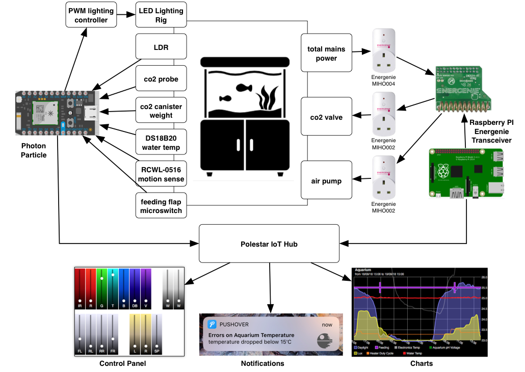
Figure 2: Schematic
Central control of the whole setup is done with Polestar - my Internet-of-Things (IoT) hub software. This is responsible for capturing and charting the data captured and well as controlling things and hosting a user interface. I recently interfaced it to Amazon Alexa to allow voice control.
Lighting
The aquarium hood hosts the micro-controller and lighting rig. There is a lot of detail here. In Figure 3 you can see the LEDs dominate the space. The LEDs are broken down into three groups. Firstly the main large aluminium heatsinks contain 8 channels of control: deep red plus IR, red, green, turquoise, blue, deep blue, violet, and cool white. The wiring is a little messy here as I’ve evolved the design a little, now favouring control over the spectrum rather than being able to control each side individually.
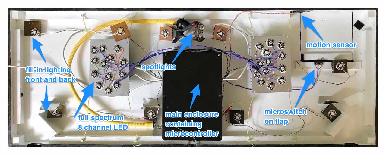
Figure 3: Flipping open the aquarium hood
Next, we have the fill-in lighting four across the front and four across the back. These are all cool white and are controlled by 4 channels: front-left, front-right, back-left, and back-right. I added these as even though the individual LEDs have a wide beam angle I found that the corners didn’t get lit well. I’ve also found creative lighting setups that involve lighting the back wall of the aquarium.
Finally, I have three channels of spot-lighting, these are warm white and have lenses on the front of the LEDs to focus the light into a narrower 45-degree beam. Two of these channels are in point down from the inside of the hood to strategic locations, and the last is blu-tacked to the side of the aquarium and pointing through the glass. This gives the impression of a low setting sun.
You can find more details of the technical setup of the lighting in an earlier post - Aquarium Lighting Controller
Co2 Setup
Infusing co2 into the water is essential for supporting the plants to grow well. Within the tank, I have a ceramic diffuser which creates micro-bubbles. These pass through the filter system and are fully dissolved into the water by the time it exits from the filter. The hardware for the co2 system is based upon the JBL ProFlora system.
The co2 is supplied by a 500g canister which sits upon a weighing scale. These tanks are about 1.7Kg when full, that reduces to 1.2Kg by the time they are empty. I built a custom scale platform from wood and a 10Kg load cell sensor connected to an HX711 module. These are a strain gauge on a lever. The HX711 module provides a highly sensitive resistance measurement connected to a 24bit analogue to digital converter. These are readily available on eBay.
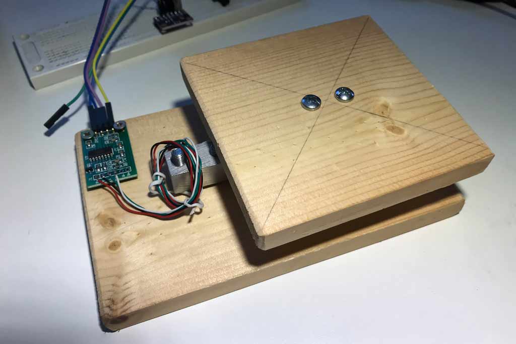
Figure 4: Load cell and HX711
The co2 canister is connected to the tank via a pressure regulator and a mains powered solenoid. This solenoid controls the flow co2 by opening and closing a valve. An Energenie MIHO002 radio-controlled socket controls power for the solenoid.
There is a daily cycle in the tank that is driven by the day-night cycle. Plants require and consume more co2 the brighter the light, and in the dark plants emit excess co2 back into the water. Because of this, it is vital that adding co2 stops before dusk. After dark, an additional Energenie MIHO002 switch turns on an air-pump. This diffuses fresh oxygen into the water and removes excess co2. Excess co2 can be dangerous to fish just as it is to humans - causing asphyxiation.
The concentration of co2 is measured indirectly by measuring the pH (acidity) of the water. The co2 in the water that dissolves as carbonic acid, the more acidic it becomes. pH probes are readily available, but they are finicky things requiring constant calibration to be accurate. I added the pH probe to the tank with the intent of just initially monitoring its voltage output. I still have not bothered to calibrate. I find it fluctuates daily.
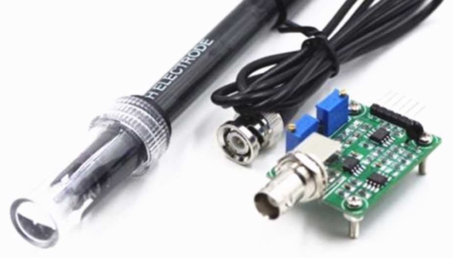
Figure 5: pH Probe
Figure 6 shows a week of data from the co2 probe charted. It does give a good indication of what is happening even without calibration. However, I wouldn’t trust its data to control the co2 solenoid.
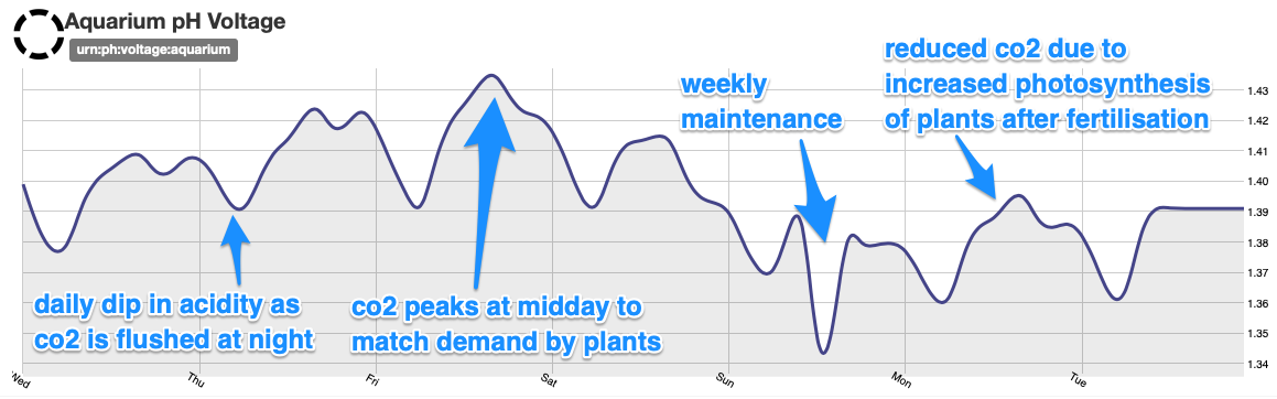
Figure 6: Uncalibrated pH sensor voltage
Other sensors
There is an array of other sensors connected to the Photon. I measure the internal light level using a light dependent resistor (LDR). This is to provide a feedback loop to check that the lighting controller is actually working, though it’s never actually failed.
I measure temperature using a waterproof DS18B20 sensor. This isn’t actually used to control anything, but Polestar does monitor it and raise an alert if it goes out of range.
I’ve placed a microswitch on the feeding flap that captures when feeding occurs this is useful if you’re forgetful and also for reminding a family member to feed the fish if I’m away.
I added a motion sensing RCWL-0516 to the front side of the hood. The idea was that I could experiment with triggering lighting effects and such when somebody was near the tank. Unfortunately, the RCWL-0516 has quite a lot of false positives. This might be because the power supply to it isn’t clean - both the photon and the pulse width modulation of the lighting create much electrical noise.
The Energenie MIHO004 is a power monitoring pass-through socket that measures the total power used by the aquarium. Power is roughly split between three components. Firstly the filtration system uses roughly 20W constantly. The 100W heater runs at between 0% and 40% duty cycle, and the remainder is lighting which varies between 0W and 70W through the daily cycle.
Polestar
Polestar is the hub that connects everything. The micro-controller in the hood autonomously controls the daily lighting cycle of the tank and interfaces to most of the sensors but everything else, software-wise, is performed in Polestar.
Polestar’s first job is to monitor all the sensors and capture this data in a time-series database making it available for charting. I showed you the raw pH chart above in figure 6, but it also generates composite charts such as figure 7 giving an overview of the status of the tank.
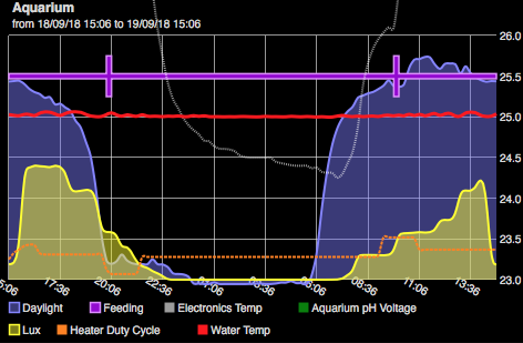
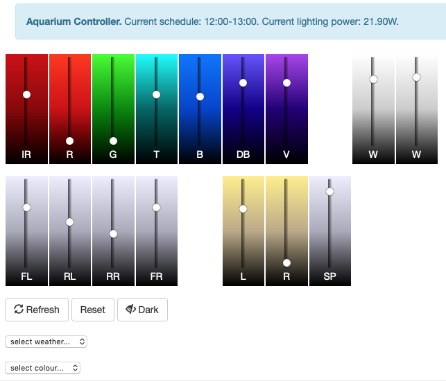
Figure 7: Daily Status Chart
The daily cycle of lighting can be overridden using a custom control panel that I developed in Polestar. This presents sliders for each of the 16 lighting channels as well as a bank of presets and some fancy weather simulation programs I’ve been playing with.